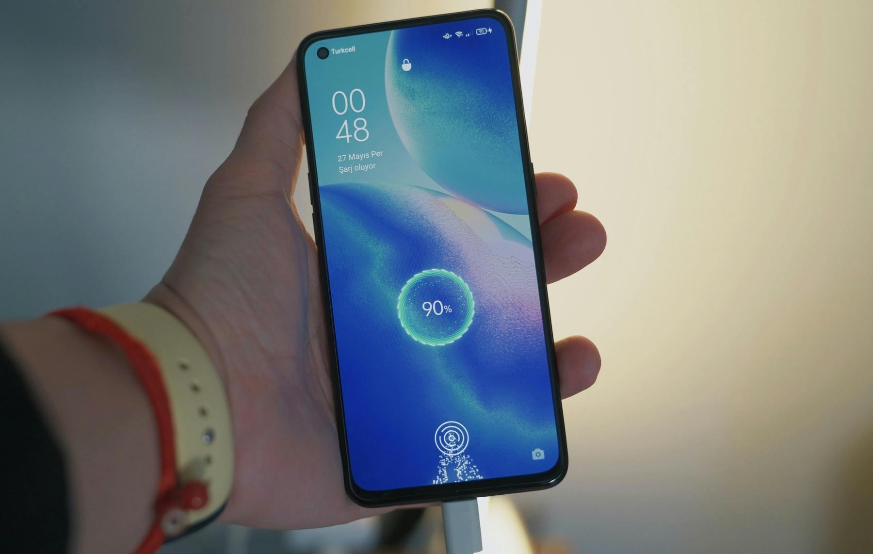
How To Maximize Battery Run Time in Mobile Electronic Devices
Design efforts to maximize battery run time typically focus on minimizing standby power, but an equal emphasis should be placed on designing for peak power.
How To Maximize Battery Run Time in Mobile Electronic Devices
Consideration of peak power requirements via careful design and battery selection can dramatically increase battery runtime and, ultimately, customer satisfaction.
Most electronic devices exhibit a pulsing behavior, where peak power is much higher than standby power. This includes mobile (i.e. battery-operated) devices.
Here are some common examples of battery-operated devices with pulsing behavior:
- Wireless sensors that periodically transmit information across a long distance
- Electric hand tools and toys with actuating motors
- Bluetooth audio speakers with high dynamic range
- Medical device pumps with backup battery supplies
A major design goal for a mobile device is to maximize battery run time (no one wants to face the ire that was directed at Apple over their phones’ battery problems). Typically, the largest design efforts to achieve this are minimizing standby power through careful selection and implementation of components with low quiescent power. An example of products that do this well are biometric sensors powered by energy harvesting. However, there should be an equal emphasis on designing for peak power, because an inability to support these peaks will result in premature battery replacement.
As a battery loses charge, its ability to deliver peak power diminishes. This is due to a property of batteries known as internal resistance. This resistance is modeled in series with the battery output, and it is a function of the battery’s size, chemistry, age, temperature, and state of charge. Figure 1, below, shows an equivalent circuit of a battery driving a simple load, with internal resistance shown as parameter ‘r.’
As the internal resistance increases, more power is dissipated across it, and less is available for the load. Eventually the internal resistance becomes so large that the battery will not be able to deliver sufficient peak power, especially in a pulsing application. A significant factor of internal resistance is state of charge — as a battery becomes depleted, its internal resistance increases. This behavior is shown in Figure 2, below.
A pulsing application requires low internal resistance for proper function. For example, consider a scenario where a 3 Volt battery needs to periodically deliver 0.5 Amps to a pulsed load such as a smoke alarm. From analysis of Figure 1, if the battery’s internal resistance is 3 Ohms, then the voltage available for the motor is 3 — (3 x 0.5) = 1.5 Volts, and the motor would not run well at all. If the battery matched the behavior shown above, it would reach this bad state (internal resistance = 3 Ohms) when it still had 60% capacity left and would already need to be replaced! This is an example of peak power limiting battery run time. Ideally, a battery should be usable across its entire range of charge.
Fortunately, there are several design techniques that can prevent this from happening.
4 Techniques to Maximize Battery Run Time in Mobile Electronic Devices
1. Peak power pulses can be reduced by introducing large capacitors near the load circuit, by spreading out discharge energy over time. This ability is limited by the size and cost of the capacitors that the device can accommodate.
2. Peak power pulses can also be reduced by slowly ramping up (e.g. soft starting) the load. This is limited by the dynamic requirements of the circuit, and how slowly it can ramp up while still functioning well.
3. Series resistance within the circuit can be reduced by careful design of connectors, wiring, and PCB layout. For very high peak power devices like motors, a small reduction of 100 milliohms can have a noticeable effect. One pro tip is to avoid using battery “spring” connectors like those shown in Figure 3 for high power applications. These connectors can have hundreds of milliohms of series resistance and thus a detrimental effect on applications with motors.
4. Peak power may be reduced by careful selection of application components. For example, try to choose wireless IC’s with lower current draw during transmit pulses, and select motors with lower startup current.
5. Finally, choose the right battery for the application. Careful consideration should be paid to internal resistance over the life of the product, to prevent premature battery replacement. Avoid battery spring connectors, like the ones pictured above, in high power applications. Good examples of variation are shown in Figures 3 and 4 below, which indicate significant differences in internal resistance for coin cell and alkaline batteries.
Compare the top chart showing alkaline AAA battery internal resistance (IR) vs depth of discharge to the one below it showing coin cell 2450 battery internal resistance (IR) vs depth of discharge. Choosing the right battery for the application is key to prevent premature battery replacement (sources: Radio Shack, Energizer).
Example
The HelmetFit football helmet inflation system contains a wireless air pump that employs several of these techniques to optimize performance and battery life. Careful selection of the internal pump (technique #4) and battery (technique #5) were combined with a soft-start algorithm (technique #2) to maximize battery life while delivering peak performance in all applications.
Internal resistance can prevent using the entire battery capacity in pulsing applications. Consideration must be paid to peak power requirements, through careful design and battery selection. These efforts can dramatically increase battery run time and customer satisfaction.
(This article was first published in Electronic Design as Designing for Peak Power in Mobile Devices.)
Learn more about Product Development Engineering Services from Delve.